Analog Stethoscope Amplifier
Using modern integrated amplifier chips, as well as a tiny switching dc power converter, to make a fully analog amplifier for stethoscopes.
Why?
This project was made for a Senior design assignment, where I had just 2 months to design and fabricate a project I found inspiring. I came up with this idea while in the back of an ambulance watching one of my coworkers using a multi-hundred dollar digital amplifier to take a patients heart rate. Even though I do not think that is the best application for that tool, there are situations in the medical field where they definitely are, and that made me curious wether a low cost analog options was possible.
Design
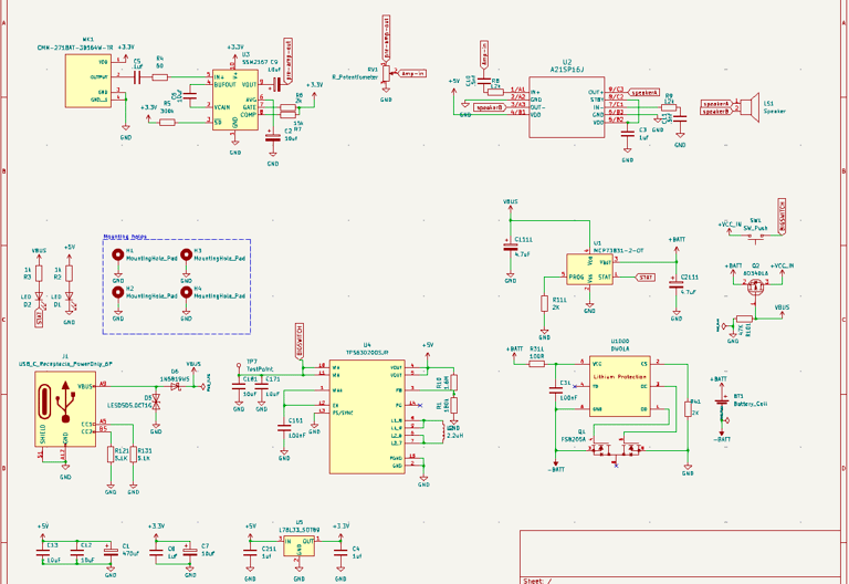
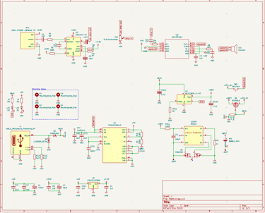
Circuit Design
I used a tiny MEMS microphone as the main sensor for this project. I used to amplifier stages to get the output of the microphone to a useable level and then had a tiny speaker as the output. I wanted an entirely analog option to cut cost and make the device easy to repair if something ever broke. The rest of the schematic is devoted to power supply and battery management with a usb-C charging and protection circuit. I fell into the trap of over-engineering this project, if I were to do it again i would cut the usb charger entirely and use an external battery charger, or even easier, a AAA battery pack.
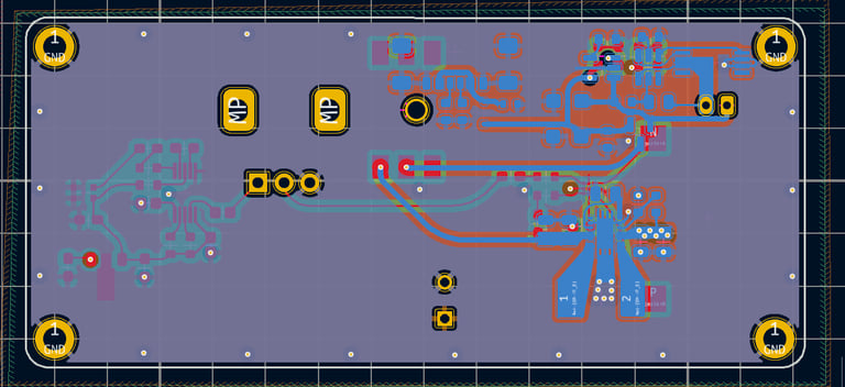
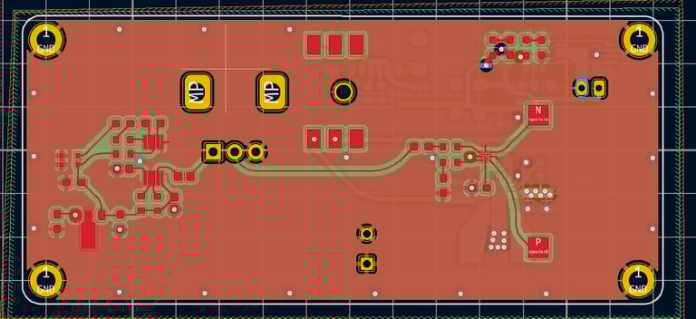
PCB Design
This PCB shows my inexperience at the time. There are elements of it that I do like, although layout generally could be improved and component selection as well. In fact, component selection may of been one of the biggest challenges of this project for me. I picked tiny advanced chips for what should have been a simple project, making troubleshooting and testing a marathon. The boards were ordered from JLC and populated by hand using a hand held iron and hot air gun. This was my first project using reflow and I actually enjoyed the process more than I though I would. However, It will be a while until I pick a BGA component for the first revision of a board.
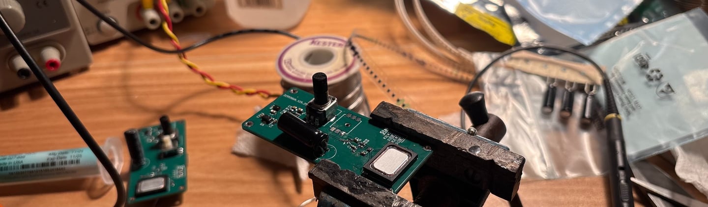
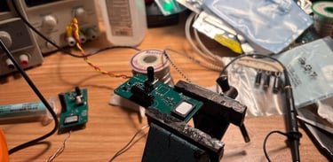
Testing
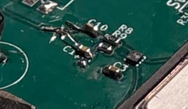
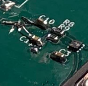
Errors made in circuit design and PCB layout made testing the board so much harder than it needed to be. With some time I was able to get both the preamplifier, amplifier, and power sections working. I wish I had more time and funding to construct a useable prototype, regardless the experience of working with new generation components, bga packages too small for hand soldering, and analog circuits I would not normally work with was invaluable. The video shows initial testing of the preamplifier and amplifier network. The photo shows the bodges necessary to make the differential amplifier work.
Results
Unfortunately most of video and photos of this project were lost when my phone at the time was smashed. Please enjoy this video that I was able to dig up from the testing phase!